Coordinated by Alain Sultan, MCC.
Introduction
The Fifth Generation of Mobile Telephony, or 5G, or 5GS, is the system defined by 3GPP from Release 15, functionally frozen in June 2018 and fully specified by September 2019.
3GPP defines not only the air interface but also all the protocols and network interfaces that enable the entire mobile system: call and session control, mobility management, service provisioning, etc. Thanks to this approach 3GPP networks can operate in an inter-vendor and inter-operator context.
5G is defined in several phases. Release 15 specifies 5G phase 1, which introduces a new radio transmission technique and other key concepts such as an industry-grade reliability, an extended modularity, or a faster response time.
All previous generations have been designed to be used by an ever wider audience, 5G is pushing out further – ready for use by all industry sectors and for time critical applications, such as autonomous driving.
To offer these capacities, and more generally to improve the user experience, 5G makes use of a set of dedicated technologies, such as "Network Function Virtualization" and "Slicing" to increase the modularity, "EDGE computing" for faster response time, Non-Terrestrial Networks (NTN) / Satellite Communications for ubiquitous coverage, etc.
The road to a fifth generation
3GPP plays a major part in the approximate once-every-decade generational progression since the first phase of mobile standards in the 1980s. Each generation has harvested improvements throughout the system, measured in 3GPP Releases – with the groups having recently starting progress on Rel-18 specifications.
As the name suggests, 3GPP started work in 1998 on the third generation of mobile, using techniques and an evolutionary path that could be embraced by all regions. This Global convergence towards the 3GPP specifications has allowed fantastic market growth and an increasing level of assurance that broadband cellular - and now the internet-of-everything - can rely on a stable and future looking standardization platform.
From an array of mobile systems for early generations, all operators are now offering 3GPP systems, with LTE (4G) delivered by over 800 operators, with 150 of them already offering 5G to their users (Source: GSAcom.com).
5G services
5G improves on the 4G services over several axis:
- Enhanced Mobile Broadband (eMBB): Higher data-rates are specified. For the downlink, up to 50 Mbps are offered for outdoor and 1 Gbps for indoor (5GLAN), with half of these values available for the uplink. A number of case studies have been under consideration, amongst them is aviation – where eMBB is helping deliver a bitrate of 1,2 Gbps to an airborne flight.
- Critical Communications (CC) and Ultra Reliable and Low Latency Communications (URLLC): In some contexts, extremely high reliability is expected. For instance, for remote control of process automation, a reliability of 99,9999% is expected, with a user experienced data rate up to 100 Mbps and an end-to-end latency of 50 ms. This is provided in particular through the Edge Computing capability.
- Massive Internet of Things (mIoT). Several scenarios require the 5G system to support very high traffic densities of devices. The Massive Internet of Things requirements include the operational aspects that apply to the wide range of IoT devices and services anticipated in the 5G timeframe.
- Flexible network operations. These are a set of specificities offered by the 5G system, as detailed in the following sections. It covers aspects such as network slicing, network capability exposure, scalability, and diverse mobility, security, efficient content delivery, and migration and interworking.
More information on these axis is provided in:
- Release 15 Description; Summary of Rel-15 Work Items (TR 21.915)
- Service requirements for the 5G system (TS 22.261)
- NR and NG-RAN Overall description; Stage-2 (TS 38.300).
This diversity of requirements, associated to the different categories of usage described above, enables the 5G system (5GS) to be useful to a new set of markets aka. "verticals", including: automotive, rail & maritime communications; transport and logistics; discrete automation; electricity distribution; public Safety; health and wellness; smart cities; media and entertainment.
In addition to the new 5G-specific services, the 5G system supports almost all the 4G LTE ones [1 – 9] and mobility between a 5G core network and a 4G core network (EPC) is supported, with minimum impact on the user experience.
Overall architecture
Schematically, the 5G system uses the same elements as the previous generations: a User Equipment (UE), itself composed of a Mobile Station and a USIM, the Radio Access Network (NG-RAN) and the Core Network (5GC), as shown in the figure below.
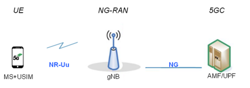
Figure 1: overview of the 5GS
The main entity of the NG-RAN is the gNB, where "g" stands for "5G" and "NB" for "Node B", which is the name inherited from 3G onwards to refer to the radio transmitter. The radio interface is named "NR-Uu" for similar reasons, although with divergences: here, "5G" is indicated by "NR" (for "New Radio") and Uu is also a name inherited from previous generations. The gNB may be further split into a gNB-Central Unit (gNB-CU) and one or more gNB- Distributed Unit(s) (gNB-DU), linked by the F1 interface.
The 5GC is here schematically represented by the AMF/UPF entity: the User Plane Function (UPF), handling the user data and, in the signalling plane, the Access and Mobility management Function (AMF) that accesses the UE and the (R)AN. Further entities of the 5GC are presented below. The reference point between the access and the core networks is called "NG". This reference point is constituted of several interfaces (mostly N2, N3), as shown below.
The 5GC architecture relies on a "Service-Based Architecture" (SBA) framework, where the architecture elements are defined in terms of "Network Functions" (NFs) rather than by "traditional" Network Entities. Via interfaces of a common framework, any given NF offers its services to all the other authorized NFs and/or to any "consumers" that are permitted to make use of these provided services. Such an SBA approach offers modularity and reusability.
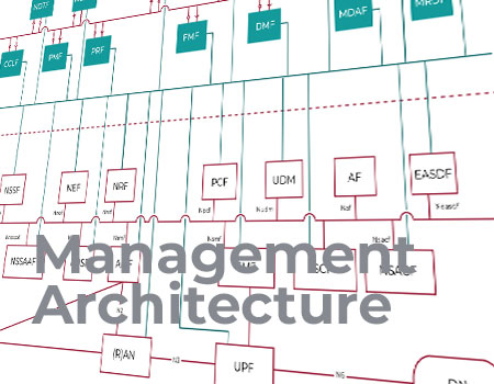
The Figure 2, extracted from ‘System architecture for the 5G System (5GS)’ (TS 23.501), shows the main NFs:
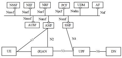
Figure 2: the 5GS architecture
In the figure above, the User Plane, i.e. the Network Functions (NFs) and elements involved in the transport of user data, is shown at the bottom level, whereas the upper part of the figure shows all the essential NFs within the signalling plane. In this first approach, the following NFs are shown:
- The four entities already introduced, i.e.: the UE, the NG-RAN or (R)AN, the UPF and the AMF
- The (external) Data Network (DN), mostly in the User Plane
- The Application Function (AF), controlling the application(s) (with possible involvement also in the user plane)
- The Session Management Function (SMF), that handles the calls and sessions, and contacts the UPF accordingly
- The Unified Data Management (UDM), functionally similar to 3G and 4G's HSS (and 2G's HLR)
- The Policy Control Function (PCF), that controls that the user data traffic does not exceed the negotiated bearer(s) capacities
- The Network Repository Function (NRF), which "controls" the other NFs by providing support for NF register, deregister and update service to NF and their services.
- The security-related NFs: Network Exposure Function (NEF), Authentication Server Function (AUSF), Security Anchor Functionality (SEAF) – see TechGuide "Security in 5G"
- The Network Slice Selection Function (NSSF) – see TechGuide "Slicing in 5G"
5G Protocol stacks
A protocol stack is defined e.g. in TS 23.501 for communications between several of these NFs, and secondary ones, not presented in the figure above. Here, we highlight some of the main ones:
Control plane: the UE-to-AMF and UE-to-SMF protocol stack
The protocol stack between the UE and the SMF, via the AMF, is shown in the next figure [TS 23.501, section 8.2]:
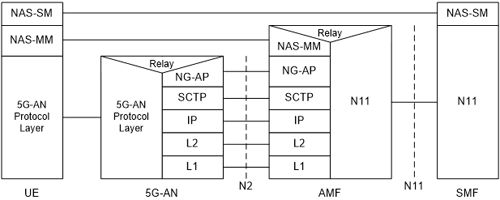
Figure 3: Control Plane protocol stack between the UE, the 5G-AN, the AMF and the SMF
NAS-SM: it supports the handling of Session Management between the UE and the SMF. It supports user plane PDU Session Establishment, modification and release. It is transferred via the AMF, and transparent to the AMF. It is defined in ‘Non-Access-Stratum (NAS) protocol for 5G System (5GS); Stage 3’ (TS 24.501).
NAS-MM: it supports registration management functionality, connection management functionality and user plane connection activation and deactivation. It is also responsible of ciphering and integrity protection of NAS signalling. 5G NAS protocol is defined in TS 24.501.
5G-AN Protocol layer: This set of protocols/layers depends on the 5G-AN. In the case of NG-RAN, the radio protocol between the UE and the NG-RAN node (eNodeB or gNodeB) is specified in the E-UTRA & E-UTRAN; ‘Overall description; Stage 2’ (TS 36.300) and the NR ‘Overall description; Stage-2’ in TS 38.300. In the case of non-3GPP access, see clause 8.2.4.
NG Application Protocol (NG-AP): Application Layer Protocol between the 5G-AN node and the AMF. NG-AP is defined in TS 38.413.
Stream Control Transmission Protocol (SCTP): This protocol guarantees delivery of signalling messages between AMF and 5G-AN node (N2). SCTP is defined in ietf RFC 4960.
Note that there is also a direct communication between 5G-AN and SMF, called N2 SM information: this is the subset of NG-AP information (not shown on the figure) that the AMF transparently relays between the 5G-AN and the SMF, and is included in the NG-AP messages and the N11 related messages.
User plane: the UE-to-AMF and UE-to-SMF protocol stack
The following figure is extracted from TS 23.501, section 8.3. It illustrates the protocol stack for the User plane transport related with a PDU Session.
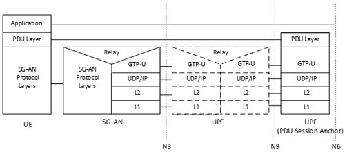
Figure 4: User Plane Protocol Stack between the UE, the 5G-AN and the UPF
PDU layer: This layer corresponds to the PDU carried between the UE and the DN over the PDU Session. When the PDU Session Type is IPv4 or IPv6 or IPv4v6, it corresponds to IPv4 packets or IPv6 packets or both of them; When the PDU Session Type is Ethernet, it corresponds to Ethernet frames; etc.
GPRS Tunnelling Protocol for the user plane (GTP U): This protocol supports tunnelling user data over N3 (i.e. between the 5G-AN node and the UPF) and N9 (i.e. between different UPFs of the 5GC) in the backbone network, details see TS 29.281. GTP shall encapsulate all end user PDUs. It provides encapsulation on a per PDU Session level. This layer carries also the marking associated with a QoS Flow defined in clause 5.7. This protocol is also used on N4 interface as defined in TS 29.244.
5G-AN protocol stack: This set of protocols/layers depends on the AN. When the 5G-AN is a 3GPP NG-RAN, these protocols/layers are defined in TS 38.401. The radio protocol between the UE and the 5G-AN node (eNodeB or gNodeB) is specified in TS 36.300 and TS 38.300. L2 is also called the "Data Link Layer" and the L1 is the "Physical Layer".
UDP/IP: These are the backbone network protocols.
The 5G radio interface
5G's radio technology is called NR (for New Radio). It is specified in TS 38.300 "NR; NR and NG-RAN Overall description; Stage-2".
For layer 1: for the downlink (DL), i.e. network to UE, NR uses OFDM with Cyclic Prefix (CP) (similar to LTE). For the uplink (UL), i.e. UE to network, OFDM can also be used, as well as DFT-s-OFDM (OFDM with Discrete Fourier Transform precoding). DFT-s-OFDM improves UL coverage but it has lower peak-to-average power ratio (PAPR) and is limited to single-layer transmission only.
Some key characteristics of 5G layer 1 is that it spreads over multiple frequency ranges, to enable deployment in frequencies on a per-country or per-region basis. The carriers are from 400 MHz up to 100 GHz, but the licensed bands are from 600 MHz up to 39 GHz. These frequencies are re-farmed analogue TV (UHF) bands and some satellites systems, without interference since used in different locations.
For terrestrial, 3 main ranges of frequencies are identified:
- Up to 1 GHz: with its better propagation characteristics, this set is intended to cover large areas, typically for rural deployment. The maximum bandwidth for one carrier is 100 MHz.
- From 1 to 6 GHz: this intermediate range is for 5G deployment in a urban or sub-urban context. Here too, the maximum bandwidth is 100 MHz.
- Higher than 6 GHz: with its poorer propagation but higher bandwidth to the user (maximum bandwidth of 400 MHz), this range is meant for dense urban environment ("hot-spot" type of coverage).
More high-level details of the 5G NR, including the layer 1, are provided in the Summary of Rel-15 Work Items: TR 21.915.
The "Non-Stand Alone" (NSA) versus the "Stand-Alone" (SA) architecture
Two deployment options are defined for 5G:
- the "Non-Stand Alone" (NSA) architecture, where the 5G Radio Access Network (AN) and its New Radio (NR) interface is used in conjunction with the existing LTE and EPC infrastructure Core Network (respectively 4G Radio and 4G Core), thus making the NR technology available without network replacement. In this configuration, only the 4G services are supported, but they enjoy the capacities offered by the 5G New Radio (lower latency, etc). The NSA is also known as "E-UTRA-NR Dual Connectivity (EN-DC)" or "Architecture Option 3". See also the clause on EDCE5.
- the "Stand-Alone" (SA) architecture, where the NR is connected to the 5G CN. Only in this configuration, the full set of 5G Phase 1 services are supported.
The NSA architecture is illustrated in the following figure.
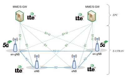
Figure 5: The NSA Architecture
The NSA architecture can be seen as a temporary step towards a "full 5G" deployment, where the 5G Access Network is connected to the 4G Core Network. In the NSA architecture, the (5G) NR base station (logical node "en-gNB") connects to the (4G) LTE base station (logical node "eNB") via the X2 interface. The X2 interface was introduced prior to Release 15 to connect two eNBs. In Release 15, it also supports connecting an eNB and en-gNB to provide NSA.
The NSA offers dual connectivity, via both the 4G AN (E-UTRA) and the 5G AN (NR). It is thus also called "EN-DC", for "E-UTRAN and NR Dual Connectivity".
In EN-DC, the 4G's eNB is the Master Node (MN) while the 5G's en-gNB is the Secondary Node (SN).
This is explained in detail on the dedicated section on NSA of this document.
The SA architecture is illustrated in the following figure.
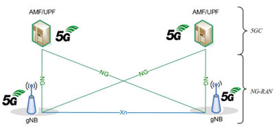
Figure 6: The SA Architecture
The SA architecture can be seen as the "full 5G deployment", not needing any part of a 4G network to operate.
The NR base stations (logical node "gNB") connect with each other via the Xn interface, and the Access Network (called the "NG-RAN for SA architecture") connects to the 5GC network using the NG interface.
Some specificities of the 5G network
The rest of this section refers to the 5G SA architecture, with the NSA being addressed in a later section.
More than a new radio interface, the 5G network introduces a number of key new technologies. Some of them are briefly introduced here:
Network Slicing: This is the ability to deploy and use simultaneously different CNs, each one specialised in the provisioning of a given set of services and/or a given set of subscribers. For instance, one slice can support the "usual" network operator’s subscribers, another slice might be dedicated to support the subscribers of a virtual operator, a third one can handle a specific service, like tracking of containers via M2M, etc.
Network Function Virtualization: As shown in Figure 2, all the Network Functions communicate through a common interface and so can be located anywhere. This allows for much greater flexibility in the network deployment. Maintenance is also greatly simplified, as a temporary NF can be easily established.
EDGE computing: Some computational power is introduced as "physically close" to the end-user as possible. Indeed, some applications such are virtual reality, factories of the future or autonomous driving, are very demanding in terms of the propagation's/network's response time. To reduce this time, some "local replications” of a main server are introduced closer to the end-user.
Going further
The 5G system is described in over a thousand 3GPP Technical Reports (TRs) and Technical Specifications (TSs).
To help you find more information, e.g. on the dynamic behaviour of 5GS (procedures, etc) or on some specific aspect of 5G, some key TRs and TSs are listed here:
- TS 22.261, "Service requirements for the 5G system".
- TS 23.501, "System architecture for the 5G System (5GS)"
- TS 23.502 "Procedures for the 5G System (5GS)
- TS 32.240 “Charging management; Charging architecture and principles".
- TS 24.501 "Non-Access-Stratum (NAS) protocol for 5G System (5GS); Stage 3"
- TS 38.300 "NR; NR and NG-RAN Overall description; Stage-2"
Referenced Specifications:
- TS 22.278, "Service requirements for the Evolved Packet System (EPS)".
- TS 22.011, "Service accessibility".
- TS 22.101, "Service aspects; Service principles".
- TS 22.185, "Service requirements for V2X services".
- TS 22.071, "Location Services (LCS); Service description".
- TS 22.115, "Service aspects; Charging and billing".
- TS 22.153, "Multimedia priority service".
- TS 22.173, "IP Multimedia Core Network Subsystem (IMS) Multimedia Telephony Service and supplementary services".
- TS 22.186, "Service requirements for enhanced V2X scenarios".
3GPP Work Plan:
See a listing of all work & study items here: https://www.3gpp.org/ftp/Information/WORK_PLAN/.
Working Groups:
All groups.
3GPP Release(s):
Rel-19
Rel-18
Rel-17
Rel-16
Rel-15
IMPORTANT NOTE: Please be aware that these pages are a snapshot of the work going on in 3GPP. The full picture of all work is contained in the Work Plan (https://www.3gpp.org/ftp/Information/WORK_PLAN/)
Updated: 11/Oct/2022 Added charging content (KF)

 Technology