Shaping the future
The 3rd Generation Partnership Project unites seven telecommunications standard development organizations, known as Organizational Partners, providing their members with a stable environment to produce the Reports and Specifications that define the 3GPP system.


-
3GPP News
-
 Japan to host TSGs#111
Feb 13, 2026
-
 RAN Working Groups in Goteborg
Feb 11, 2026
-
 Working Groups go to GOA
Feb 09, 2026
-
Featured News
Spotlight on...

IALA joins 3GPP as MRP
The International Organization for Marine Aids to Navigation (IALA), an intergovernmental organization dedicated to promote the safe, economic and efficient movement of vessels - through harmonised Marine Aids to Navigation, has today joined 3GPP as a Market Representation Partner (MRP), to build on the Rel-16 Maritime Communication Services over 3GPP system study work and inputs from IALA on Requirements for later releases.

The 3GPP Video Collection
The latest videos with our leadership were recorded in September, 2025. All three interviews - with TSGs SA, CT and RAN Chairs are posted to our Vimeo site. In that same location you will find a library of interviews and wish-you-were-here post cards, recorded by the team since 2008.
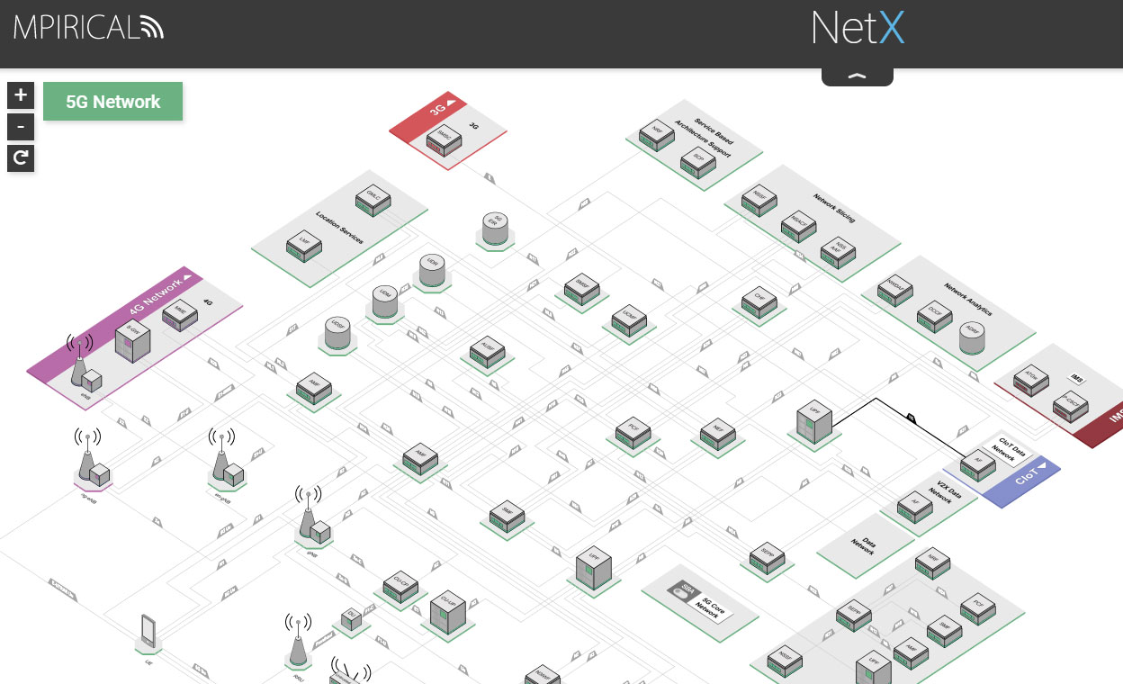
Free access to 5G NetX
We have decided to continue providing a link to the 5G version of the NetX network map via our website.
Have a look and let us know whether it was useful to you. Any feedback will help us to ensure that this resource is relevant to the broad 3GPP community.
3GPP Global Membership
| < 20 | 20 | 40 | 60 | 80 | 100 | 120 | 140 | > 160 |
-
Australia
- Australian Signals Directorate
ETSI - CSIRO
ETSI - Dept of Home Affairs
ETSI - Motorola Mobility Aus Pty. Ltd
ETSI - Myriota
ETSI - Softel Systems
ETSI - Telstra Limited
ETSI
-
Austria
- BMWKMS
ETSI - Frequentis AG
ETSI - Kapsch TrafficCom AG
ETSI - ORS
ETSI - Tait Europe Limited
ETSI - T-Mobile Austria GmbH
ETSI
-
Belgium
- A.S.T.R.I.D. SA/NV
ETSI - Apple Benelux B.V. - Belgium
ETSI - BIPT
ETSI - BNE
ETSI - Cisco Systems Belgium
ETSI - European Commission
ETSI - EUTC
ETSI - InterDigital Belgium. LLC
ETSI - Nokia Belgium
ETSI - Orange Belgium
ETSI - Proximus Plc
ETSI - PSCE
ETSI
-
Botswana
- BOCRA
ETSI
-
Brazil
- MOTOROLA MOBILITY BRAZIL
ETSI
-
Canada
- Bell Mobility
ETSI - Ericsson Canada Inc.
ATIS - InterDigital Canada
ATIS - ISED
ETSI - Nokia Canada
ATIS - Public Safety Canada
ETSI - RadiSys
ETSI - RN-CI
ATIS - Rogers Communications Canada
ETSI - TELUS
ATIS - TerreStar Solutions Inc.
ATIS - VoiceAge Corporation
ETSI
-
Chile
- MQUEST-TECHNOLOGIES
ETSI
-
China
- ABP, NRTA
CCSA - ABS
CCSA - Apple
CCSA - Apple (Guizhou)
CCSA - Apple (Ulanqab)
CCSA - Apple Computer Trading Co. Ltd
CCSA - Apple R&D
CCSA - Apple Solutions
CCSA - Apple Trading
CCSA - AsiaInfo
CCSA - AsiaInfo Technologies Inc
ETSI - ASR
CCSA - ASTRI
ETSI - ASUSTEK COMPUTER (SHANGHAI)
CCSA - Baicells Technologies Co. Ltd
CCSA - Beijing Lenovo Software Ltd.
CCSA - BEIJING SAMSUNG TELECOM R&D
CCSA - Beijing Xiaomi Electronics
CCSA - Beijing Xiaomi Mobile Software
CCSA - Beijing Xiaomi Mobile Software
ETSI - Beijing Xiaomi Software Tech
CCSA - BJTU
CCSA - BTL Inc.
ETSI - BTPDI
CCSA - BUPT
CCSA - BYD
CCSA - Bytedance
CCSA - CAICT.
CCSA - CALTTA
CCSA - CATT
CCSA - CATT
ETSI - CBN
CCSA - CENC
CCSA - CEPRI
CCSA - Chengdu OPPO Telecommunication
CCSA - China Broadnet
CCSA - China Mobile (Hangzhou) Inf.
CCSA - China Mobile (Suzhou) Software
CCSA - China Mobile Com. Corporation
CCSA - China Mobile E-Commerce Co.
CCSA - China Mobile Group Device Co.
CCSA - China Mobile lnfo.Tech.Co. Ltd
CCSA - China Mobile M2M Company Ltd.
CCSA - China Southern Power Grid Co.
CCSA - China Telecom Corporation Ltd.
CCSA - China Telecommunications
ETSI - China Telecommunications Corp.
CCSA - China Unicom
CCSA - Chongqing University
CCSA - CICT
CCSA - CICT
ETSI - CICT Mobile
CCSA - CICTCI
CCSA - CITC
CCSA - CMDI
CCSA - Comba
CCSA - CQUPT
CCSA - CSCN
CCSA - CU Digital Technology
CCSA - CUC
CCSA - CUG
CCSA - Cybercore
CCSA - Datang Linktester Technology
CCSA - Datang Linktester Technology
ETSI - Datang Mobile Com. Equipment
ETSI - Datang Mobile Com. Equipment
CCSA - DOCOMO Beijing Labs
CCSA - Douyin
CCSA - Ericsson (China)
CCSA - E-surfing Digital
CCSA - Esurfing IoT
CCSA - Fiberhome Technologies Group
CCSA - FRDC
CCSA - Fudan University
CCSA - GEESPACE
CCSA - GUANGDONG GENIUS TECHNOLOGY CO
CCSA - Guangdong OPPO Mobile Telecom.
CCSA - Hangzhou Mengyuxiang
CCSA - HiSilicon Technologies Co. Ltd
CCSA - Honor
CCSA - Honor
ETSI - HTC Communications Co., Ltd.
CCSA - Huawei Device Co., Ltd
CCSA - HUAWEI TECHNOLOGIES Co. Ltd.
ETSI - HuaWei Technologies Co., Ltd
CCSA - Hytera Communications Corp.
CCSA - IPLOOK
CCSA - iQoo
CCSA - Lansus
CCSA - Lenovo (Beijing) Ltd
CCSA - Lenovo (Shanghai) Information
CCSA - Lenovo (Tianjin) Ltd.
CCSA - Lenovo Future Communications
CCSA - Lenovo Information Technology
CCSA - Maxscend
CCSA - MaxWave Micro
CCSA - MediaTek (Chengdu) Inc.
CCSA - MediaTek (Hefei) Inc.
CCSA - MediaTek (Shenzhen) Inc.
CCSA - MediaTek (Wuhan) Inc.
CCSA - MediaTek Beijing Inc.
CCSA - Motorola Mobile Com (Beijing)
CCSA - Motorola Mobile Com Technology
CCSA - Nanjing vivo Software Tech.
CCSA - NERCDTV
CCSA - NJIT
CCSA - Nokia China
CCSA - Nubia Technology Co.,Ltd
CCSA - OnePlus
CCSA - OnePlus
ETSI - OPPO
ETSI - OPPO (chongqing) Intelligence
CCSA - OPPO Beijing
CCSA - PCI
CCSA - Peking University
CCSA - Pengcheng Laboratory
CCSA - PKUSZ
CCSA - PML
CCSA - Purplevine Innovation Co. Ltd
CCSA - Quanray
CCSA - Quectel
CCSA - QWCT
CCSA - Realme (Shenzhen)
CCSA - Realme Shenzhen
ETSI - SageRAN
CCSA - SAICT
CCSA - Samsung Guangzhou Mobile R&D
CCSA - Samsung Nanjing
CCSA - Samsung Shenzhen
CCSA - Sanechips
CCSA - SCAT
CCSA - SEU
CCSA - Shanghai Chen Si Electronics
CCSA - Shanghai Jiao Tong University.
CCSA - Shanghai Tejet Com Technology
CCSA - Shenzhen Heytap
CCSA - SIA
CCSA - SmarterMicro Inc.
CCSA - Southwest Jiaotong university
CCSA - Spreadtrum
CCSA - SRTC
CCSA - SSST
CCSA - Starpoint
CCSA - SZPU
CCSA - TCL
CCSA - TD Tech Ltd
CCSA - Tencent
CCSA - Tencent Cloud
CCSA - The University of Hong Kong
ETSI - Tongji University
CCSA - TOWE Wireless
ETSI - Transsion Holdings
CCSA - ubinexus
CCSA - UESTC
CCSA - Unicom Broadband Online
CCSA - Unicompay
CCSA - UNISOC
CCSA - UNISOC Beijing
CCSA - USTB
CCSA - Vanchip
CCSA - vivo Mobile Com. (Chongqing)
CCSA - vivo Mobile Communication (H)
CCSA - vivo Mobile Communication (S)
CCSA - vivo Mobile Communication Co.,
CCSA - vivo Software Technology
CCSA - vivo Wisdom Technology
CCSA - VSENS
CCSA - WHVCSE
CCSA - Wuhan Hongxin Technology
CCSA - Xiamen Sanan Integr. Circuit
CCSA - Xiaomi Communications
CCSA - Xiaomi Digital Technology
CCSA - Xiaomi Electronic Software
CCSA - Xiaomi EV Technology
CCSA - Xiaomi Technology
CCSA - Xidian University
CCSA - XNET
ETSI - X-Net
CCSA - Zhejiang University
CCSA - ZTE Corporation
CCSA - ZTE Corporation
ETSI
-
Czech Republic
- Czech Telecommunication Office
ETSI - Mesaqin.com s.r.o (Ltd.)
ETSI - Samsung Electronics Czech
ETSI
-
Denmark
- Anemone Technology
ETSI - Apple AB Denmark
ETSI - Cobham SatCom A/S
ETSI - Gatehouse Satcom A/S
ETSI - Nokia Denmark
ETSI - Verizon Denmark
ETSI
-
Estonia
- Jio Platforms
ETSI
-
Finland
- Bittium Wireless Ltd.
ETSI - Erillisverkot
ETSI - ETS-Lindgren Europe
ETSI - InterDigital Finland Oy
ETSI - LG Electronics Finland
ETSI - Magister Solutions Ltd
ETSI - MediaTek Finland
ETSI - Nokia Corporation
ETSI - TRAFICOM
ETSI - Verizon Finland
ETSI - VTT
ETSI - WE Certification Oy
ETSI
-
France
- Airbus
ETSI - Apple France
ETSI - AQSACOM S.A.S.
ETSI - ATEME
ETSI - B-Com
ETSI - BOUYGUES Telecom
ETSI - CANON Research Centre France
ETSI - CEA
ETSI - Cisco Systems France
ETSI - CNES
ETSI - Cobelty
ETSI - Cosmian
ETSI - Dolby France SAS
ETSI - EDF Recherche et Développement
ETSI - EFORT
ETSI - ENENSYS
ETSI - Ericsson France S.A.S
ETSI - ETELM
ETSI - EURECOM
ETSI - Eutelsat
ETSI - GW
ETSI - Hewlett-Packard Enterprise
ETSI - Huawei Technologies France
ETSI - IDEMIA
ETSI - Institut Mines-Telecom
ETSI - Institute VEDECOM
ETSI - Intel Corporation SAS
ETSI - InterDigital France R&D, SAS
ETSI - Intersec
ETSI - IRT Saint Exupery
ETSI - ITRON SAS
ETSI - Kontron Transportation France
ETSI - LEGRAND FRANCE
ETSI - LG Electronics France
ETSI - Meta Platforms, Inc - FR
ETSI - MINISTERE DE L'INTERIEUR
ETSI - Ministère Economie et Finances
ETSI - Mitsubishi Electric RCE
ETSI - Motorola Mobility France S.A.S
ETSI - MVG Industries
ETSI - Nokia France
ETSI - Orange
ETSI - Qualcomm France
ETSI - Samsung Electronics France SA
ETSI - Sequans Communications
ETSI - SGDSN
ETSI - TDF
ETSI - TEXAS Instruments
ETSI - THALES
ETSI - Ubiik
ETSI - Union Inter. Chemins de Fer
ETSI - Verizon France
ETSI - Xiaomi Technology France
ETSI - ZTE FRANCE SASU
ETSI
-
Germany
- 450connect GmbH
ETSI - Accenture
ETSI - aconnic
ETSI - adare GmbH
ETSI - Apple GmbH
ETSI - AUMOVIO
ETSI - BDBOS
ETSI - BfV
ETSI - BKA
ETSI - BMW AG
ETSI - BMWE
ETSI - BSI (DE)
ETSI - cetecom advanced GmbH
ETSI - Comprion GmbH
ETSI - Deutsche Telekom AG
ETSI - DLR
ETSI - DOCOMO Communications Lab.
ETSI - Dolby Germany GmbH
ETSI - Ericsson GmbH, Eurolab
ETSI - European Patent Organisation
ETSI - FAU
ETSI - Fraunhofer FOKUS
ETSI - Fraunhofer HHI
ETSI - Fraunhofer IIS
ETSI - G+D MS
ETSI - Gigaset Technologies
ETSI - Harman GmbH
ETSI - HEAD acoustics GmbH
ETSI - HUAWEI TECH. GmbH
ETSI - IBM Europe
ETSI - INFINEON TECHNOLOGIES
ETSI - Intel Deutschland GmbH
ETSI - IPCom GmbH & Co.KG
ETSI - John Deere GmbH & Co. KG
ETSI - JSI GmbH
ETSI - Kepler
ETSI - LG Electronics Deutschland
ETSI - LKA Niedersachsen
ETSI - MediaTek Germany GmbH
ETSI - Montsecure
ETSI - Motorola Mobility Germany GmbH
ETSI - Motorola Solutions Germany
ETSI - Nexburg
ETSI - Nokia Germany
ETSI - PANASONIC R&D Center Germany
ETSI - Qualcomm Germany
ETSI - ROBERT BOSCH GmbH
ETSI - ROHDE & SCHWARZ
ETSI - Samsung Electronics GmbH
ETSI - Sennheiser electronic SE
ETSI - SHURE Europe GmbH
ETSI - Siemens AG
ETSI - SWR
ETSI - sysmocom
ETSI - Telefonica Germany GmbH
ETSI - Telekom Deutschland GmbH
ETSI - Valeo
ETSI - Vodafone GmbH
ETSI - Volkswagen AG
ETSI - Xiaomi Technology Germany GmbH
ETSI - ZITiS
ETSI - Zollkriminalamt (ZKA)
ETSI - ZTE Deutschland
ETSI
-
Greece
- CERTH
ETSI - FOGUS
ETSI - OTE S.A
ETSI
-
Hungary
- Ericsson Hungary Ltd
ETSI - Nokia Hungary
ETSI - SSNS
ETSI
-
India
- Astrome Technologies Pvt Lt
TSDSI - Bharti Airtel Limited
TSDSI - CAPGEMINI
TSDSI - C-DAC
TSDSI - C-DOT
TSDSI - CEWiT
TSDSI - CLUPAV Scientific
TSDSI - Consort Digital
ETSI - Department of Telecom
TSDSI - DNN Wireless
TSDSI - Elena Geo Tech
TSDSI - Ericsson India Private Limited
TSDSI - ERNET India
TSDSI - Free Stream Technologies
TSDSI - Huawei Telecommunication India
TSDSI - IIIT Bangalore
TSDSI - IIIT Delhi
TSDSI - IIT Bhilai
TSDSI - IIT Bombay
TSDSI - IIT Delhi
TSDSI - IIT Kanpur
TSDSI - IIT, Kharagpur
TSDSI - Indian Institute of Tech (H)
TSDSI - Indian Institute of Tech (M)
TSDSI - iSignal Research Labs
TSDSI - ISRO
TSDSI - Lekha Wireless Solutions
TSDSI - Mediatek India Technology Pvt.
TSDSI - MeitY
TSDSI - Meta India
TSDSI - Motorola Mobility India Ltd
ETSI - Nokia Solutions & Networks (I)
TSDSI - OptimusLogic
TSDSI - QAIG
TSDSI - QClairvoyance Quantum Labs
TSDSI - Qualcomm India Pvt Ltd
TSDSI - Reliance Jio
TSDSI - Samsung R&D Institute India
TSDSI - Scytale Alpha
TSDSI - Signalchip Innovations Pvt.
TSDSI - SMOAD
TSDSI - Susan Future
TSDSI - Syniverse
TSDSI - TCS
TSDSI - Tech Mahindra Limited
TSDSI - TechPhosis
TSDSI - Tejas Network Limited
TSDSI - Vaan Megam
TSDSI - Wireless 4 Scale
TSDSI - Wisig Networks Pvt Ltd
TSDSI - ZTE
TSDSI
-
Ireland
- Amdocs Software Systems Ltd
ETSI - Apple Distribution Intl Ltd
ETSI - DTS Licensing Limited
ETSI - Google Ireland Limited
ETSI - Intel Ireland
ETSI - L.M. Ericsson Limited
ETSI - Meta Ireland
ETSI - Microsoft Ireland
ETSI - Qualcomm Technologies Ireland
ETSI - Red Hat Limited
ETSI - ST Engineering iDirect
ETSI - Vodafone Ireland Plc
ETSI - Xilinx Ireland
ETSI
-
Israel
- Cognyte
ETSI - Elbit Systems
ETSI - Gilat
ETSI - Softil Ltd
ETSI - Wiliot Ltd.
ETSI
-
Italy
- Ericsson Telecomunicazioni SpA
ETSI - Fastweb S.p.A.
ETSI - FiberCop
ETSI - Leonardo SpA
ETSI - MIMIT
ETSI - QUALCOMM Europe Inc. - Italy
ETSI - TELECOM ITALIA S.p.A.
ETSI - Telit Communications S.p.A.
ETSI - UNIBO
ETSI - Xiaomi Technology Italy srl
ETSI - ZTE Italia
ETSI
-
Japan
- Anritsu Corporation
ARIB - CNC
ETSI - DENSO CORPORATION
ARIB - DTCY
TTC - Ericsson Japan K.K.
ARIB - Facebook Japan G.K.
ARIB - Fujitsu Limited
ARIB - Fujitsu Limited
TTC - Huawei Tech. Japan, K.K.
TTC - HUAWEI Technologies Japan K.K.
ARIB - ITOCHU Techno-Solutions Corp
TTC - Japan Radio Co., Ltd
ARIB - KDDI Corporation
ARIB - KDDI Corporation (TTC)
TTC - Kyocera Corporation
ARIB - Kyoto University
ETSI - Mitsubishi Electric Co.
ARIB - Mitsubishi Electric Corp
TTC - Murata Manufacturing Co Ltd.
ARIB - NEC Corporation
ETSI - NEC Corporation (ARIB)
ARIB - NEC Corporation.
TTC - NHK
ARIB - NICT
ARIB - Nokia Japan
ARIB - NTT
TTC - NTT DOCOMO INC.
TTC - NTT DOCOMO INC..
ARIB - Oki Electric Industry Co. Ltd.
TTC - Panasonic Holdings Corporation
ARIB - QUALCOMM JAPAN LLC.
ARIB - Rakuten Mobile, Inc
ARIB - SAMSUNG R&D INSTITUTE JAPAN
ARIB - SHARP Corporation
ARIB - SKY Perfect JSAT Corporation
ARIB - SoftBank Corp.
ARIB - Sony Corporation
ARIB - Sony Group Corporation
ARIB - Sumitomo Elec. Industries, Ltd
ARIB - Tomorrow's Creation Labs
ARIB - TOYOTA MOTOR CORPORATION
TTC - UTokyo
ETSI - ZTE Japan K.K.
ARIB - ZTE JAPAN K.K.
TTC
-
Korea (republic Of)
- Ajou University
TTA - Ericsson Korea Partners Co Ltd
TTA - ETRI
TTA - Eurofins KCTL
ETSI - Ewha Womans University
TTA - Google Korea LLC
TTA - Hanbat National University
TTA - Huawei Technologies (Korea)
TTA - Hyundai Motor Company
TTA - ITL
TTA - KAIST
TTA - Kookmin University
TTA - Korea Testing Laboratory
TTA - KRRI
TTA - KT Corp.
TTA - LG Electronics Inc.
TTA - LG Uplus
TTA - MediaTek Korea Inc.
TTA - MOIP
TTA - MTCC
TTA - Nokia Korea
TTA - Qualcomm Korea
TTA - RICHTEK KOREA
TTA - Samsung Electronics Co., Ltd
TTA - Seoul National University
TTA - SK Telecom
TTA - SOLiD
TTA - Soongsil University
TTA - SyncTechno Inc.
ETSI - Uangel
TTA - WILUS Inc.
TTA - Yonsei University
TTA - ZTE Korea Limited
TTA
-
Luxembourg
- Amazon Web Services
ETSI - OQTEC
ETSI - POST Luxembourg
ETSI - Sisvel
ETSI - SnT - University of Luxembourg
ETSI
-
Mexico
- Altan Redes S.A.P.I. de C.V.
ETSI - Ericsson Telecom S.A. de C.V.
ATIS - Nokia Mexico
ATIS
-
Netherlands
- Apple Benelux B.V.
ETSI - ESA
ETSI - Europol
ETSI - EVE Compliancy Solutions
ETSI - Group 2000
ETSI - KPN N.V.
ETSI - Logius
ETSI - MinEA
ETSI - NCI Agency
ETSI - Netherlands Police
ETSI - NXP Semiconductors Netherlands
ETSI - Odido
ETSI - Palo Alto Networks
ETSI - Philips International B.V.
ETSI - PIDS
ETSI - Qualcomm Tech. Netherlands B.V
ETSI - Reflection B.V.
ETSI - SpaceX
ETSI - TNO
ETSI - Verizon Netherlands
ETSI - Xiaomi Technology Netherlands
ETSI
-
New Zealand
- Spark NZ Ltd
ATIS
-
Norway
- Ceragon Networks AS
ETSI - NCIS
ETSI - Nkom
ETSI - Nordic Semiconductor ASA
ETSI - TELENOR ASA
ETSI
-
Poland
- Centralny Osrodek Informatyki
ETSI - LG Electronics Polska
ETSI - Nokia Poland
ETSI - Samsung Electronics Polska
ETSI - T-Mobile Polska S.A.
ETSI - Xiaomi Technology (Polska) sp.
ETSI
-
Portugal
- Connected
ETSI - MEO
ETSI
-
Romania
- Orange Romania
ETSI - Vodafone Romania S.A.
ETSI
-
Serbia
- RATEL
ETSI
-
Singapore
- ASTRUM MOBILE PTE. LTD.
ETSI - CSA
ETSI - IMDA
ETSI - SUTD
ETSI
-
Slovak Republic
- Ministry of Transport SR
ETSI
-
Slovenia
- SIST
ETSI
-
Spain
- BARADINE
ETSI - CTTC
ETSI - DEKRA
ETSI - EMITE
ETSI - Ericsson España S.A.
ETSI - HISPASAT SA
ETSI - Ministry for Digital - Spain
ETSI - Motorola Mobility España SA
ETSI - NEMERGENT
ETSI - QUALCOMM Europe Inc. - Spain
ETSI - Samsung Electronics Iberia SA
ETSI - Sateliot
ETSI - TELEFONICA S.A.
ETSI - UMA
ETSI - UPV/EHU
ETSI - VALID SOLUCIONES TECNOLÓGICAS
ETSI - Verizon Spain
ETSI - VIVO MOBILE COMMUNICATION IBER
ETSI - Xiaomi Technology Spain S.L
ETSI
-
Sweden
- BeammWave AB
ETSI - Bluetest AB
ETSI - DIGG
ETSI - Ericsson AB.
ATIS - Ericsson LM
ETSI - Huawei Technologies Sweden AB
ETSI - Husqvarna AB
ETSI - Intel Sweden AB
ETSI - MediaTek Sweden AB
ETSI - NDRE
ETSI - Polisen
ETSI - PTS
ETSI - Qualcomm Sweden
ETSI - RISE
ETSI - Samsung Electronics Nordic AB
ETSI - Sectra Communications AB
ETSI - Security Service
ETSI - SOS Alarm
ETSI - Telia Company AB
ETSI - Trafikverket
ETSI - Verizon Sweden
ETSI
-
Switzerland
- Apple Switzerland AG
ETSI - EBU
ETSI - Embotech AG
ETSI - Ofcom (CH)
ETSI - Schindler
ETSI - Semtech Neuchatel SA
ETSI - STMicroelectronics
ETSI - SWISSCOM
ETSI - Verizon Switzerland AG
ETSI
-
Taiwan, Province Of China
- Acer Incorporated
ETSI - Bureau Veritas ADT
ETSI - CCU
ETSI - CHTTL
ETSI - Far EasTone Telecommunication
TTC - III
ETSI - ISSDU
ETSI - ITRI
ETSI - MediaTek Inc.
ETSI - NTU
ETSI - NYCU
ETSI - Sporton International Inc
ETSI - Tron Future Tech Inc.
ETSI - Wistron Corporation
ETSI - WNC Corporation
ETSI
-
Türkiye
- ASELSAN
ETSI - IMU
ETSI - Plan-S
ETSI - Turk Telekomunikasyon A.S.
ETSI - TURKCELL
ETSI - Vestel
ETSI - Vodafone Telekomünikasyon A.S.
ETSI
-
Uganda
- CGL
ETSI
-
United Arab Emirates
- Khalifa University
ETSI - THURAYA TELECOM CO.
ETSI
-
United Kingdom
- 6GIC
ETSI - Aalyria
ETSI - AccelerComm Ltd
ETSI - Anritsu EMEA Ltd
ETSI - Apple (UK) Limited
ETSI - ARTICLE19
ETSI - BAE Systems AI Ltd
ETSI - BBC
ETSI - Broadcom (EU)
ETSI - BT plc
ETSI - CAMBRIDGE CONSULTANTS LTD
ETSI - Catapult
ETSI - CKH IOD UK LIMITED
ETSI - Dolby Laboratories Inc.
ETSI - DSIT
ETSI - EA Consult Services Ltd
ETSI - EchoStar
ETSI - Element Materials Technology
ETSI - Ericsson Limited
ETSI - Federated Telecoms Hub
ETSI - HOME OFFICE
ETSI - Huawei Tech.(UK) Co.. Ltd
ETSI - Huawei Technologies R&D UK
ETSI - ICS
ETSI - Imperial College London
ETSI - Inmarsat
ETSI - Intel Corporation (UK) Ltd
ETSI - InterDigital, Europe, Ltd.
ETSI - Keysight Technologies UK Ltd
ETSI - LG Electronics UK
ETSI - Maketh Secure Limited
ETSI - MediaTek UK
ETSI - Meta Platforms, Inc - UK
ETSI - Motorola Mobility UK Ltd.
ETSI - Motorola Solutions UK Ltd.
ETSI - National Technical Assistance
ETSI - NCSC
ETSI - NEC Europe Ltd
ETSI - NEC Telecom MODUS Ltd.
ETSI - Network Rail
ETSI - Nokia UK
ETSI - NOVAMINT
ETSI - NPL
ETSI - Ofcom (U.K.)
ETSI - Orange UK
ETSI - Pairpoint
ETSI - Qualcomm Technologies Int
ETSI - Queens University Belfast
ETSI - Samsung R&D Institute UK
ETSI - Sensus UK
ETSI - Sepura Ltd
ETSI - SGS Wireless
ETSI - Sony Europe Limited
ETSI - Telesat International Limited
ETSI - Toshiba
ETSI - UL VS Ltd
ETSI - University of Bristol, SIL
ETSI - University of Sheffield
ETSI - Unumplus
ETSI - Verizon UK Ltd
ETSI - ViaSat Satellite Holdings Ltd
ETSI - VIAVI Solutions
ETSI - VODAFONE Group Plc
ETSI - Xiaomi Technology UK Limited
ETSI
-
United States
- Anterix
ATIS - APCO International
ATIS - Apple Inc
ATIS - AST SpaceMobile
ATIS - AT&T
ATIS - AT&T Labs, Inc
ATIS - AT&T Services, Inc.
ATIS - Axyom.Core
ETSI - Boost Mobile Network
ATIS - C Spire Wireless
ATIS - CableLabs
ETSI - Cadence Design Systems Inc.
ETSI - Charter Communications, Inc
ATIS - CIS
ETSI - CISA ECD
ATIS - Cisco Systems
ATIS - Cohere Technologies
ATIS - Comcast
ATIS - Comtech Telecommunications Cor
ATIS - Confluence Technology Group
ATIS - Dartmouth College
ETSI - DeepSig Inc
ATIS - Dell Technologies
ATIS - Ericsson Inc.
ATIS - F5
ETSI - Fainity Innovation
ATIS - FCC
ATIS - FirstNet
ATIS - Futurewei
ETSI - Futurewei Technologies
ATIS - GLOBALSTAR Inc.
ETSI - GTRC
ETSI - Intel
ATIS - InterDigital Communications
ATIS - InterDigital New York
ATIS - InterDigital Pennsylvania
ATIS - InterDigital Washington DC
ATIS - InterDigital, Inc.
ETSI - Iridium Satellite LLC
ATIS - JMA Wireless
ATIS - Johns Hopkins University APL
ATIS - Kratos Defense
ATIS - L3Harris Technologies
ATIS - Ligado Networks
ETSI - Lockheed Martin
ATIS - MATRIXX Software
ETSI - Mavenir
ETSI - MediaTek Technology USA Inc.
ATIS - MediaTek USA
ATIS - Meta USA
ATIS - Microchip Technology, Inc.
ATIS - MidWave Wireless
ATIS - MITRE Corporation
ETSI - MITRE-FFRDC
ATIS - Motorola Mobility LLC
ETSI - National Instruments Corp.
ETSI - National Spectrum Consortium
ATIS - Netscout Systems Inc.
ETSI - NextNav
ATIS - Nightwing
ATIS - NIST
ATIS - Nokia
ATIS - Nokia Americas
ATIS - NTIA
ATIS - NVIDIA
ATIS - Ofinno, LLC
ATIS - Omnispace
ATIS - ONE Media 3.0 LLC
ATIS - Oracle Corporation
ETSI - OTD_US
ATIS - PHY Wireless
ATIS - Polaris Wireless
ATIS - Qorvo
ETSI - Qualcomm Atheros, Inc.
ATIS - Qualcomm Incorporated
ATIS - Qualcomm Innovation Center Inc
ATIS - Qualcomm Technologies
ATIS - Rakuten Symphony
ATIS - Samsung Research America
ATIS - SES
ATIS - Skylo Technologies
ATIS - Skyworks Solutions Inc.
ETSI - Southern Linc.
ATIS - Spirent Communications
ETSI - SS8
ETSI - Teradyne
ATIS - Texas A&M University
ETSI - Tiami Networks
ATIS - T-Mobile USA
ETSI - T-Mobile USA Inc.
ATIS - TOYOTA Info Technology Center
ETSI - TransUnion
ATIS - U.S. Department of Defense
ATIS - U.S. Department of Transport.
ATIS - U.S. National Security Agency
ATIS - Union Telephone Company
ATIS - US DHS Science & Technology
ATIS - Valid8
ETSI - XGN
ETSI
0
Countries0
Organizational Partner Members0
Number delegates at meetings this year0
3GPP Meetings this year0
3GPP Specifications0
3GPP Change Requests this year